Spazzole strip a spirale
Spazzole strip a spirale
Generalità
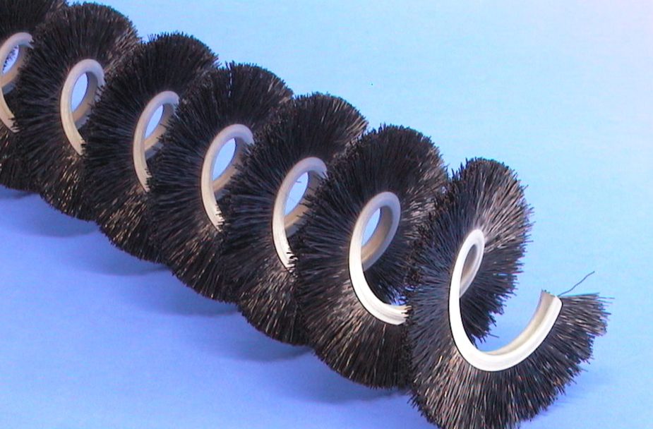
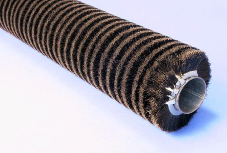
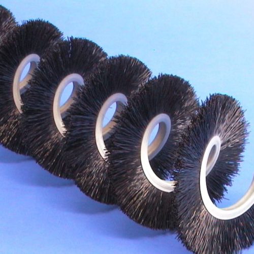
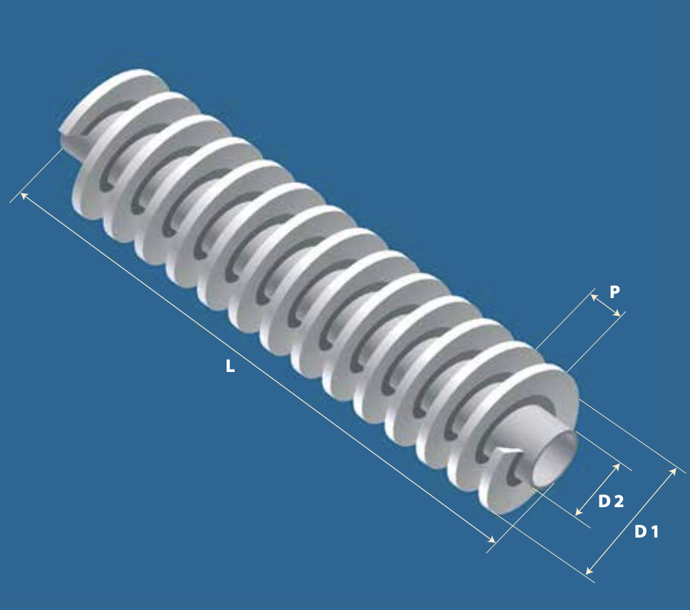
Avvolgendo un nastro strip su un nucleo cilindrico metallico si ottiene una spirale che nel suo insieme costituisce una spazzola a rullo. Se la spirale viene smontata dal nucleo metallico, si ottiene una spazzola flessibile (tipo molla) detta ‘spirale libera’.
Le spazzole strip a spirale sono utilizzate per:
- rulli di elevata densità; rulli di dimensioni molto grandi
- rulli completamente metallici per elevate temperature
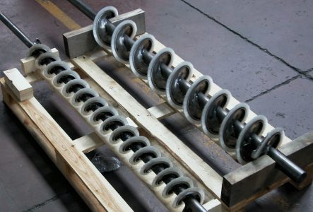
- spazzole a coclea per trasporto materiale
- spirali a passo largo per pulizia di superfici delicate
Il passo della spirale P (vedi figura) è il parametro che maggiormente influisce sulla densità della spazzola strip. Non sempre, comunque, si richiede una spazzola molto densa. Ad esempio se essa deve asportare detriti e scaricarli facilmente, il passo dovrà essere sufficientemente grande da impedire ai detriti stessi di accumularsi tra le spire.
Il valore minimo di P coincide con quello della base B. Il valore massimo è invece funzione del diametro di avvolgimento D2: maggiore è D2 maggiore può essere il passo massimo.
Si possono fissare i seguenti limiti: Pmin = B ; Pmax = D2
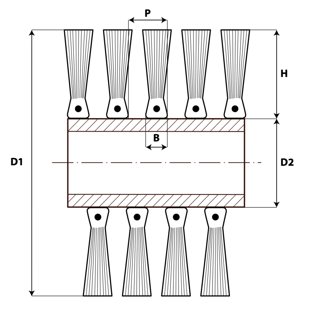
Esiste un valore minimo di D2 al di sotto del quale lo strip non può essere avvolto.
Questo valore limite dipende dalla base B, ed è riportato in Tabella (base in ferro zincato). Per basi inox i valori di D2min della Tabella vanno raddoppiati. Per quanto riguarda il diametro massimo D1 della spazzola, generalmente non è possibile superare il valore D1=1000mm.
Diametro di avvolgimento (mm)
| NASTRO SEMPLICE | |||||||||||||
|---|---|---|---|---|---|---|---|---|---|---|---|---|---|
| B | 5 | 6 | 8 | 10 | 13 | 14 | 17 | 20 | |||||
| D2 min | 15 | 20 | 25 | 25 | 90 | 90 | 160 | 160 |
Oltre che per definire la densità della spazzola, il passo di avvolgimento può essere sfruttato per svolgere una funzione meccanica di trasporto. Se infatti P è sufficientemente grande da contenere del tutto o in parte i pezzi da trattare, la spazzola si comporterà come una coclea, ed alla rotazione sarà associato uno spostamento trasversale del materiale. È quindi importante, in questo caso, specificare se l’avvolgimento deve essere destrorso o sinistrorso. Vi possono infine essere due spirali (destra e sinistra) convergenti al centro della spazzola, con l’effetto di convogliare sulla mezzeria o alle due estremità.
La soluzione spazzola-coclea è particolarmente indicata in tutti quei casi in cui si debba trasportare materiale particolarmente delicato e per la bassa rumorosità. Per progettare una spazzola a coclea data la quantità di prodotto da trasportare è molto utile la seguente formula.
Se si vuole muovere una portata di materiale V [l /min] con una spazzola che ruota a n [rpm] si dovrà mantenere un passo di avvolgimento almeno pari a:
P ≥ (4.000.000 V) / (π n e (D1² – D2²)) + B [mm] Dove e è il fattore di riempimento della coclea, con e prossimo a 0 a coclea vuota ed e=1 a coclea piena.
Un altro dato importante da conoscere in fase di progetto è la velocità di rotazione a cui si può portare un rullo strip. Purtroppo questo dato dipende, oltre che dai materiali, dal carico utilizzato sulla spazzola e dal coefficiente di attrito filamento-superficie. È quindi necessario calcolare la velocità limite di volta in volta in base ai parametri noti. In generale si può dire che una spazzola strip a rullo abbia una velocità limite più elevata di una corrispondente spazzola punzonata. Siamo a disposizione per fornirvi i necessari dati di progetto.
In caso di elevate velocità occorre realizzare un campione e testarlo in condizioni di sicurezza.
Video e immagini
GALLERIA
Vuoi richiedere un’offerta?
Sei interessato a ricevere maggiori informazioni e ad essere ricontattato da un nostro operatore specializzato?
Richiedi ora la tua offerta

Vuoi richiedere un’offerta?
Sei interessato a ricevere maggiori informazioni e ad essere ricontattato da un nostro operatore specializzato?
Richiedi ora la tua offerta
Domande frequenti
Qual è il vantaggio di usare una spazzola invece di un altro oggetto deformabile?
La caratteristica peculiare della spazzola è che la superficie di lavoro è costituita da milioni di elementi singoli, che sono l’estremità dei singoli filamenti.
Questo conferisce alla spazzola una adattabilità che nessun altro elemento, per quanto deformabile, può avere.
Quanto deve interferire la spazzola sul pezzo da lavorare?
Dipende da vari fattori. In estrema sintesi si può dire che 2 mm è un buon compromesso. L’importante è che i filamenti della spazzola lavorino “di punta” e non sul fianco.
Un mazzetto di filamento si può staccare dal corpo spazzola?
A seconda dei materiali usati e delle dimensioni, esiste un carico limite a trazione che un singolo mazzetto può sopportare.
Oltre questo limite il mazzetto si stacca, quindi la spazzola va calcolata a seconda dell’utilizzo. Si può aumentare moltissimo questo limite costruendo spazzole “cucite” o “legate” a mano, dove invece che un elemento di ancoraggio singolo si mette un filo di acciaio continuo.
È più economica una spazzola punzonata o una strip?
Non c’è una risposta univoca. Parlando ad es.di spazzole cilindriche la spazzola strip è in genere più economica quando le dimensioni sono importanti (es.oltre il metro di lunghezza). Per piccole dimensioni le spazzole punzonate sono sicuramente più adatte e convenienti.
È possibile che un singolo filamento si sfili dal mazzetto contaminando il prodotto?
Può succedere solo se la spazzola ha un difetto di fabbricazione, come d’altra parte ogni altro tipo di oggetto (ad es. un rullo fatto con lamelle di silicone di cui una è difettosa e si spezza).
Quando è importante che non avvenga alcuna contaminazione è opportuno utilizzare fibre sintetiche (non naturali) con diametro maggiore o uguale a 0.15 mm.
Quale morbidezza o durezza di spazzola posso ottenere?
Praticamente si possono avere tutti i gradi di durezza, da morbidissima a durissima. Infatti la durezza è data dalla combinazione tra il diametro del filamento, la sua lunghezza libera e la densità dei mazzetti.
È possibile avere una spazzola certificata “alimentare”?
Certamente, possiamo fornire certificazioni FDA o FOOD GRADE e rintracciabilità del filamento.
È possibile avere una spazzola certificata ATEX?
Purtroppo no, in quanto è l’insieme macchina + spazzola a dover essere certificata ATEX, non la sola spazzola.
E’ comunque possibile fornire i materiali che il certificatore richiede, ad es. basi conduttive, filamenti conduttivi ecc…
È possibile “rigenerare” una spazzola consumata?
In linea generale è possibile, bisogna però valutare se è economicamente conveniente, e non sempre lo è. Inoltre, nel caso di una spazzola punzonata, è sconsigliabile rigenerare la spazzola più di due volte per non ridurre la tenuta dei mazzetti.

